

FynoriX1511 Engineering Guide
Power Configuration & Application Guide
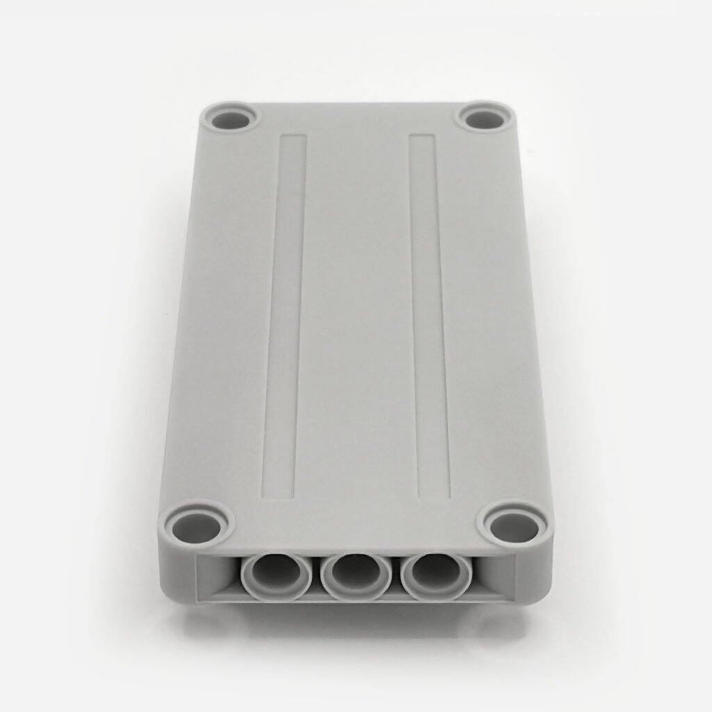
Looking for product specifications, package options or purchasing information? View the FynoriX1511 Power Brick product page.
Important Safety Notice
InfiLinX is not hot-pluggable. Always switch OFF all FynoriX1511 modules before connecting, disconnecting, or reconfiguring an InfiLinX connection.
Fully connect the InfiLinX chain first, then power on the modules. Hot-plugging InfiLinX may permanently damage the charging/input circuitry of a connected FynoriX1511 module.
Chapter 1 — Design Philosophy & System Overview
1.1 Why FynoriX1511 Exists
Traditional battery boxes often combine energy storage, control functions and electrical connections in a single enclosure.
This integrated approach is simple, but it can influence the entire structure of a model. The battery box may determine the position of the chassis, interior, bodywork or control components, particularly in compact or mechanically complex builds.
FynoriX1511 follows a different design approach.
It was developed as a compact, independent energy module whose primary function is to provide regulated electrical power. Control functions remain separate and can be selected according to the requirements of the model.
This separation allows the power system to be arranged around the available space rather than requiring the model to be built around a large integrated battery box.
FynoriX1511 was designed as the smallest independent energy unit in the system.
Its slim 7.8 mm profile and 35 g weight allow it to be positioned in areas that may not accommodate a conventional battery box while preserving its role as an independent and replaceable power module.
1.2 Modular Power Architecture
The system separates the principal electrical functions into independent modules.
Energy Module
      ↓
Controller
      ↓
Motor or Electrical Load
The operating principle is straightforward:
The battery provides power.
The controller controls.
The motor creates movement.
Each module performs its own function independently.
FynoriX1511 provides the energy required by the system.
A compatible receiver, controller or switch determines how that energy is delivered.
The motor or other connected device converts the supplied electrical energy into movement, light or another output.
Separating these functions provides several practical advantages:
- each module can be selected according to the application;
- the energy module is not restricted by the location of the controller;
- different control systems can be used without changing the fundamental role of the battery;
- future interface and control modules can be developed around a consistent energy platform;
- the complete system can be expanded without requiring every function to be integrated into one enclosure.
This modular architecture does not assume that one electrical arrangement is suitable for every model.
Instead, it allows the builder to select the combination of energy, control and output components that best matches the application.
1.3 The First Energy Module
FynoriX1511 is the first energy module in a broader modular electrical platform.
Its primary responsibilities are clearly defined:
- store electrical energy;
- provide regulated 9 V output;
- remain independent from the control system;
- support flexible installation;
- provide a consistent energy foundation for compatible modules.
FynoriX1511 is not intended to replace the role of a receiver, controller or motor driver.
The separation of energy and control is intentional.
A compact vehicle may require a small receiver positioned near the motor. A display model may use a simple switch. A future application may use a different controller or interface system.
In each case, the energy module continues to perform the same function.
This means that the battery can remain useful even when the control requirements of the model change.
Power Functions compatibility is only the starting point.
The Power Functions interface provides an established connection method for existing motors, receivers, switches and lighting components. However, the long-term design principle is not limited to one connector or control standard.
FynoriX1511 is intended to become the energy foundation of a future modular electrical platform in which compatible controllers, interfaces and other system components can perform their own specialised functions.1.4 The Battery Adapts to the Model
A central principle of the FynoriX1511 design is:
The battery should adapt to the model—not the model to the battery.
Because the energy module is separate from the controller, it does not need to be installed beside a switch, receiver or control interface.
It can be positioned wherever suitable space is available and connected to the remaining electrical system.
Possible installation areas may include:
- compact chassis structures;
- body panels;
- side structures;
- cockpits;
- engine compartments;
- spaces above or below the drivetrain;
- other space-constrained assemblies.
This flexibility is particularly useful in models where internal space is divided into several small areas rather than one large battery compartment.
The energy module may be positioned according to:
- available internal volume;
- weight distribution;
- accessibility;
- cable routing;
- structural requirements;
- the layout of the mechanical system.
The objective is not simply to make the battery smaller.
The objective is to reduce the influence of the battery on the overall model architecture.1.5 Different Applications, Different Configurations
Models differ significantly in size, operating purpose and electrical demand.
A compact display mechanism, a lightweight vehicle, a train layout and a heavy multi-motor model do not require the same power arrangement.
This does not indicate a limitation in the energy module.
It reflects the fact that different applications have different operating requirements.
A modular power system allows the configuration to be selected according to the application rather than applying one fixed solution to every model.
Within the FynoriX1511 platform, different configurations may be used for different purposes:
- a single energy module for standard applications;
- capacity expansion when longer operating time is required;
- multiple-output configurations for applications with greater startup demand.
The purpose of this guide is to explain how these configurations relate to the requirements of the complete model.
There is no universal power configuration—only the configuration that best matches the application.1.6 InfiLinX within the Modular Ecosystem
InfiLinX is the modular interconnection interface for compatible components within the expanding CONCEPTBRICK electrical ecosystem.
Rather than being limited to one type of module or one transmission function, InfiLinX is designed to provide a common connection framework between compatible system components.
Depending on the connected modules and configuration, InfiLinX may carry power or control signals. Future compatible applications may also support data transmission. The specific function and compatibility will be defined for each product as it is introduced.
InfiLinX is an interconnection interface, not a charging interface. Connected modules must be charged through their own designated charging ports.
This guide focuses on its current application with FynoriX1511.
For the current FynoriX1511 application, InfiLinX is not hot-pluggable. All connected energy modules must be powered OFF before an InfiLinX connection is made, removed, or changed.
When used with FynoriX1511, InfiLinX carries power between multiple energy modules to increase total stored energy and extend operating time.
Instead of replacing FynoriX1511 with a physically larger battery enclosure, additional energy modules can be distributed across different areas of a model while operating as one capacity-expanded system.
This approach is consistent with the wider modular design philosophy:
- preserve modularity;
- maintain compact installation;
- allow the energy system to scale with the application;
- support distributed energy-module placement;
- avoid forcing every model to use the same battery size.
The current FynoriX1511 capacity-expansion configuration is explained in Chapter 3.
1.7 System Design Principle
FynoriX1511 should be considered part of a complete electrical and mechanical system.
The energy module, controller, motor and mechanical structure each perform different functions, but the final result depends on how these elements work together.
The modular design philosophy can therefore be summarised as follows:
Select the model requirements
            ↓
Choose the appropriate energy configuration
            ↓
Choose the appropriate control method
            ↓
Integrate the system into the available structure
This approach allows the electrical system to be adapted to the model from the beginning of the design process.
It also allows the configuration to be changed later if the operating requirements of the model change.
1.8 Before You Continue
The following chapters explain how to apply this modular design philosophy in practical model design.
Chapter 2 — Understanding Motor Requirements
Introduces motor running current, stall current and general compatibility reference values.
Chapter 3 — Selecting the Right Power Configuration
Explains the differences between a single FynoriX1511, InfiLinX Capacity Expansion and Multi-Battery Stacked PF Output.
Chapter 4 — Best Practices & Operating Recommendations
Provides concise recommendations for charging, installation, system optimisation and normal protection behaviour.
Together, these chapters provide a practical framework for matching the power system to the application.
The objective is not to use the largest possible configuration.
The objective is to select the simplest configuration that reliably meets the requirements of the model.
Chapter 2 — Understanding Motor Requirements
2.1 Why Motor Current Matters
A motor does not draw a fixed amount of current.
Its electrical demand changes according to the mechanical load placed on it. The same motor may require relatively little current while rotating freely, but substantially more current during startup, acceleration or heavy-load operation.
Motor-current information is therefore useful for comparing different motor types and estimating the general demands of an application.
However, motor type alone does not determine the required power configuration.
The final electrical demand also depends on:
- the number of motors;
- whether motors start simultaneously;
- vehicle or mechanism weight;
- gear ratio;
- drivetrain efficiency;
- wheel or track resistance;
- operating conditions.
2.2 Running, Startup and Stall Current
Motor-current specifications are commonly described using two reference conditions.
Running Current
Running current is the current drawn while the motor is rotating normally.
It varies continuously according to the mechanical load.
A motor operating a small, efficient mechanism will generally draw less current than the same motor installed in a heavy or high-resistance drivetrain.
Startup Current
When a motor starts from rest, its speed is initially zero and its current demand can rise substantially above its normal running current.
In a lightweight and efficient mechanism, this condition may last only briefly. In a heavy vehicle, tracked drivetrain or loaded mechanism, tyre resistance, gearing, friction and mechanical inertia may keep the motor close to its stall condition for longer during startup.
Startup current should therefore be considered separately from normal running current. It represents a short-duration application demand rather than a normal continuous operating condition.
Stall Current
Stall current is the current drawn when the motor is powered but prevented from rotating.
This is an extreme reference condition and is not intended to represent normal continuous operation.
Stall-current data is useful because it shows the upper electrical demand that a motor may approach during severe loading.
2.3 Application-Oriented Motor Current Test
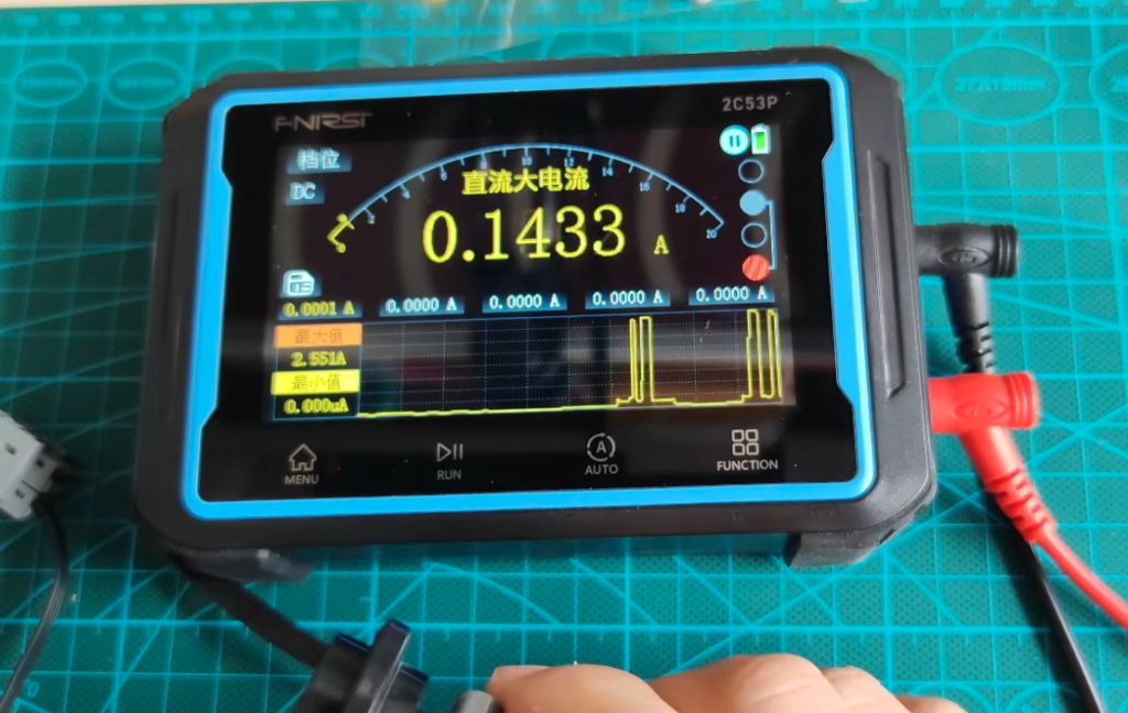
The following measurements were recorded with individual motors operating from a nominal 9 V supply.
Resistance was progressively applied to the motor output to simulate the short-duration high-resistance condition that may occur when a heavy vehicle, tracked drivetrain or loaded mechanism begins moving.
| Motor | Observed Free-Running Current | Highest Current Observed During Simulated High-Resistance Startup | Typical Applications |
|---|---|---|---|
| PF Micro Motor | 0.10 A | 0.60 A | Small mechanisms and light-duty functions |
| PF M Motor | 0.13 A | 1.50 A | General Technic mechanisms |
| PF XL Motor | 0.14 A | 2.50 A | Heavy vehicles and high-torque applications |
| PF L Motor | 0.17 A | 2.70 A | Performance-oriented drivetrains |
| PF Buggy Motor | 0.14 A | 2.80 A | High-speed RC-style applications |
These results are application-oriented observations rather than standardised motor specifications.
The highest recorded value represents a short-duration current observed while resistance was applied. It should not be interpreted as a universal stall-current rating, a continuous operating current or a guaranteed value for every motor of the same type.
Actual current may vary according to motor condition, manufacturing tolerance, temperature, measurement response, actual voltage at the motor terminals and the mechanical resistance applied.
These measurements show how motor demand can rise substantially above free-running current during a demanding startup condition.
2.4 General Compatibility Guide
The following table provides a practical starting point for selecting a FynoriX1511 configuration.
| Motor | Compatibility Rating | General Guidance |
| PF Micro Motor | ✅ Recommended | Suitable for normal light-duty applications |
| PF M Motor | ✅ Recommended | Suitable for most applications with an efficient mechanical system |
| PF XL Motor | ⚠ Application Dependent | Configuration depends on model weight, motor quantity and gearing |
| PF L Motor | ⚠ Application Dependent | Configuration depends on drivetrain design and operating load |
| PF Buggy Motor | 🔧 Model-Specific Evaluation | Requirements depend strongly on vehicle design, gearing and operating conditions |
Compatibility Legend
| Rating | Meaning |
| ✅ Recommended | Suitable for most normal applications |
| ⚠ Application Dependent | The appropriate configuration depends on the complete model |
| 🔧 Model-Specific Evaluation | The mechanical and electrical system should be evaluated together |
These ratings do not represent a maximum supported motor quantity.
For example, one heavily loaded motor may create greater demand than several lightly loaded motors.
2.5 Why Startup Demand Is Higher
When a motor starts from rest, it has not yet developed rotational speed.
During this short period, its current demand may be substantially higher than its normal running current.
Higher startup demand may occur during:
- initial movement from rest;
- rapid acceleration;
- simultaneous startup of multiple motors;
- climbing;
- moving a heavy load;
- recovering after an obstacle;
- sudden direction changes.
This does not mean the motor continuously operates at stall current.
It means that short-duration demand should be considered when selecting the power configuration.
The test method described in Section 2.3 is intended to reproduce this short-duration high-resistance condition. It is closer to the startup demand encountered in some heavy or mechanically resistant models, but it is not a standardised dynamometer or stall-current test.
2.6 Motor Type Is Only One Factor
Two models using the same motor can have very different electrical requirements.
For example:
- a lightweight vehicle with a simple drivetrain may operate with relatively low demand;
- a heavier vehicle using the same motor may require greater startup support;
- a high-speed gear ratio may increase motor load;
- a well-reduced and efficient drivetrain may reduce the required current;
- multiple motors starting together may create greater short-duration demand than the same motors starting separately.
2.7 Interpreting the Reference Values
The motor table can be used to answer three basic questions:
Is the application generally light or demanding?
Micro and M motors are commonly used in light- and medium-duty mechanisms.
L, XL and Buggy motors are more frequently used in drivetrains and applications with higher performance requirements.
Will several motors operate together?
The combined running current may remain moderate, but simultaneous startup can create a higher short-duration requirement.
Is the motor likely to operate near its mechanical limit?
A motor operating close to stall will draw more current and produce more heat than one operating within an appropriate speed and torque range.
These questions provide a useful starting point before selecting the configuration described in Chapter 3.
2.8 Important Reference Notes
The observed current values and compatibility ratings in this chapter:
- are approximate engineering references;
- do not guarantee performance in a particular model;
- do not define a universal maximum number of motors;
- do not replace testing under realistic operating conditions;
- should be considered together with the mechanical design of the model;
- represent measurements from specific motor samples under an application-oriented test method;
- should not be interpreted as universal motor specifications or continuous-current ratings.
A higher stall-current value does not automatically mean that a motor is incompatible with FynoriX1511.
It indicates that the application may require closer consideration of motor quantity, startup conditions and power configuration.
Similarly, a motor with a lower reference current may still create high demand if the mechanism is blocked, heavily loaded or inefficiently geared.
2.9 Summary
Motor current changes according to operating load.
Running current represents normal rotation, while stall current represents an extreme condition in which the motor cannot rotate.
Startup demand may briefly approach the higher end of the motor’s current range, especially when:
- several motors start together;
- the model is heavy;
- the drivetrain places significant load on the motors;
- rapid acceleration is required.
Motor-current data is therefore an important reference, but it is only one part of the configuration process.
The next chapter explains how to combine motor requirements, operating time and model characteristics to select the appropriate FynoriX1511 power configuration.Chapter 3 — Selecting the Right Power Configuration
3.1 Different Applications Require Different Configurations
Different models place different demands on their power systems.
A compact mechanism may prioritise installation space and weight. A display model may require longer operating time. A heavy vehicle or multi-motor drivetrain may require greater support during startup.
FynoriX1511 uses a modular design that allows the power configuration to match the application.
The three principal configurations are:
- Single FynoriX1511 for standard applications;
- InfiLinX Capacity Expansion for longer operating time;
- Multi-Battery Stacked PF Output for applications with greater short-duration startup demand.
These configurations serve different purposes.
There is no universal power configuration suitable for every model. The correct configuration is the one that best matches the intended application.3.2 Standard Configuration
Single FynoriX1511
A single FynoriX1511 is the recommended starting point for most models.
It provides:
- regulated 9 V output;
- 4800 mWh energy capacity;
- short-term peak output of 15.3 W;
- short-term PF output current of up to 1.7 A;
- 7.8 mm thickness;
- 35 g weight.
Typical applications include:
- compact vehicles;
- general Technic mechanisms;
- display models;
- lighting systems;
- small construction models;
- light- and medium-load motor applications.
If one energy module provides the required performance and operating time, no additional configuration is necessary.
3.3 Capacity-Oriented Configuration
InfiLinX Capacity Expansion with FynoriX1511
Some applications operate correctly with one FynoriX1511 but require longer operating time.
In these applications, multiple FynoriX1511 energy modules can be connected through InfiLinX to increase total stored energy and extend runtime.
Designate one FynoriX1511 as the main power module, identified as P1.
Important — InfiLinX is not hot-pluggable.
Before making any InfiLinX connection, switch OFF all FynoriX1511 modules.
Build and fully connect the complete InfiLinX chain while all modules are powered OFF. Confirm that all connectors are fully inserted, and only then power on the modules.
Never connect an InfiLinX cable to P1 or another module while a connected upstream module is already powered on. Hot-plugging may permanently damage the charging/input circuitry.
Build the InfiLinX chain toward P1 by following the marked input and output ports:
- connect the InfiLinX OUT port of P2 to the InfiLinX IN port of P1;
- connect the InfiLinX OUT port of P3 to the InfiLinX IN port of P2;
- continue in the same manner for each additional module.
Connection direction:
P3 OUT → P2 IN
P2 OUT → P1 IN
P1 PF Output → Switch / Receiver / Controller → Motor or Electrical Load
Power OFF → Connect the complete InfiLinX chain → Power ON
One InfiLinX cable is required for each additional module in the continuous chain.
The InfiLinX IN and OUT ports must not be confused with the separate FynoriX PF output port. Only the PF output connected to P1 is used as the main output in this capacity-expansion configuration.
Connected FynoriX1511 modules → P1 PF Output Cable → Switch / Receiver / Controller → Motor or Electrical Load
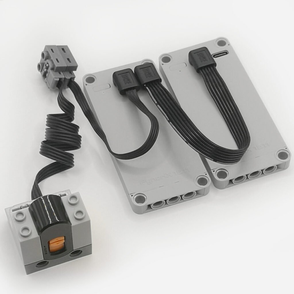
In this configuration, InfiLinX carries power between the connected energy modules but does not provide a charging function.
Before connecting the modules:
- fully charge each FynoriX1511 separately through its own USB-C charging port;
- make sure all modules have a similar state of charge;
- switch OFF all modules;
- inspect the InfiLinX cables and connectors;
- build the complete InfiLinX chain while all modules remain powered OFF;
- confirm that all connectors are fully inserted;
- only then power on the modules.
InfiLinX Capacity Expansion with FynoriX1511 is primarily used to:
- increase total stored energy;
- extend operating time;
- support distributed energy-module placement;
- preserve compact and modular installation.
Typical applications include:
- exhibitions;
- train layouts;
- continuous lighting;
- automated displays;
- long-duration demonstrations.
The main PF output remains regulated at 9 V. InfiLinX does not increase the peak current or power available from that PF output.
Its purpose in the current FynoriX1511 configuration is additional capacity and longer runtime rather than greater short-duration startup power.
3.4 High-Startup Applications
Multi-Battery Stacked PF Output
Some applications create substantial mechanical resistance at the moment of startup.
Examples include:
- heavy vehicles starting from rest;
- tracked drivetrains;
- several motors starting simultaneously;
- mechanisms beginning operation under load;
- rapid acceleration;
- aggressive gear ratios;
- drivetrains with high initial resistance.
Under these conditions, the motor may briefly operate close to its stall condition.
The application-oriented measurements in Section 2.3 illustrate how motor current can rise sharply when resistance is applied during startup, even though the motor draws relatively little current while rotating freely.
As explained in Chapter 2, motor current increases significantly as motor speed decreases. When the motor approaches stall, its instantaneous current demand may be several times higher than its normal running current.
This high current is caused by the mechanical operating condition of the motor. It is not an indication of abnormal battery performance.
FynoriX1511 provides up to 1.7 A of short-term current through its PF output. If the motor’s instantaneous demand exceeds this operating range, the internal protection system may interrupt the output as intended.
For applications that naturally produce greater startup demand, connect each FynoriX1511 module using its own FynoriX PF Output Cable, then stack the PF output connectors directly together.
Connect a compatible PF receiver, switch or controller to the same stacked PF connection, then connect the motor or other electrical load after that controlled component.

This allows multiple FynoriX1511 modules to contribute to the same PF circuit and can provide greater available power during short-duration startup demand than a single module.
The regulated output voltage remains 9 V.
Actual current contribution depends on:
- the state of charge of each module;
- internal resistance;
- connector and cable resistance;
- temperature;
- manufacturing tolerances;
- the characteristics of the connected load.
The available current or power should not be assumed to increase linearly with the number of connected modules.
3.5 Configuration Selection Guide
| Application Requirement | Recommended Configuration |
|---|---|
| Compact or standard model | Single FynoriX1511 |
| General Technic vehicle or mechanism | Begin with a single FynoriX1511 |
| Longer operating time | InfiLinX Capacity Expansion |
| Exhibition, train or continuous display | InfiLinX Capacity Expansion |
| Multiple motors starting simultaneously | Consider Multi-Battery Stacked PF Output |
| Heavy vehicle or demanding startup | Optimise the drivetrain, then evaluate Stacked PF Output |
| Blocked or repeatedly stalled mechanism | Correct the mechanical condition first |
| Stable operation throughout the intended duty cycle | No configuration change is required |
| Continuous external power for exhibitions or display models | USB-C to PF Adapter |
| Workbench motor testing without battery operation | USB-C to PF Adapter |
These recommendations provide general starting points. Actual requirements depend on the complete model, including its weight, gearing, mechanical efficiency, motor quantity and operating conditions.
For applications that require continuous external power rather than battery operation, a USB-C to PF Adapter may be used with a compatible 9 V USB-C PD power source. The adapter is an alternative power source and is not part of a FynoriX1511 multi-battery configuration. It must not be connected to the same powered PF circuit as a FynoriX1511 or another battery box.
3.6 Motor Configuration Reference
The following table provides general starting configurations for commonly used Power Functions-compatible motors.
The table should not be interpreted as a fixed motor-to-battery requirement. The appropriate Configuration depends on the complete model rather than the motor type alone.
| Motor Configuration | Recommended Starting Configuration | When to Consider Stacked PF Output |
| PF Micro Motor | 1 × FynoriX1511 | Normally unnecessary unless several motors operate together |
| PF M Motor | 1 × FynoriX1511 | Consider 2 modules when multiple motors start simultaneously under load |
| PF L Motor | 1 × FynoriX1511 | Consider 2 modules for heavy vehicles, rapid acceleration or multiple motors |
| PF XL Motor | 1 × FynoriX1511 | Consider 2 modules for tracked models, heavy startup or multiple motors |
| PF Buggy Motor | Application-dependent | Consider 2-module Stacked PF Output for demanding drive applications |
| Multiple PF Micro or M Motors | Begin with 1 × FynoriX1511 | Consider 2 modules when combined startup demand is high |
| Multiple PF L, XL or Buggy Motors | Model-specific evaluation | Consider 2-module Stacked PF Output when motors start simultaneously under load |
A motor used in an efficient and lightweight model may require less startup support than the same motor used in a heavy or high-resistance drivetrain.
The number of energy modules should therefore not be selected from stall-current values alone.
Stall current represents an extreme motor condition, not normal continuous operation.
3.7 Optimising the Complete System
The power configuration and mechanical design should be considered together.
Before selecting a multi-battery configuration, confirm that:
- gears are correctly aligned;
- axles rotate freely;
- wheels and tracks are not binding;
- the selected gear ratio is suitable for the load;
- the drivetrain does not contain unnecessary resistance;
- motors are not repeatedly held at stall;
- the model does not carry unnecessary weight.
A blocked or heavily restricted mechanism should be corrected rather than compensated for with additional energy modules.
However, some models naturally produce high startup demand even with a correctly designed drivetrain. In these applications, Multi-Battery Stacked PF Output provides a modular method of matching the power configuration to the operating requirement.
For accurate evaluation:
- fully charge the FynoriX1511;
- test the completed model under realistic operating conditions;
- include normal startup and simultaneous motor operation;
- evaluate whether the model requires longer runtime or greater startup support.
3.8 Multi-Battery Connection Notes
InfiLinX Capacity Expansion and Multi-Battery Stacked PF Output are different configurations and should be connected according to their respective instructions.
Before using either multi-module configuration:
- fully charge each FynoriX1511 separately;
- make sure all modules have a similar state of charge;
- inspect all cables and connectors;
- confirm that the relevant connectors are correctly aligned and fully inserted;
- switch OFF all modules before connecting, disconnecting, or changing any multi-module configuration.
When using InfiLinX Capacity Expansion:
- use one InfiLinX cable for each additional module;
- use P1 as the main PF output;
- connect each additional module’s OUT port to the IN port of the preceding module, continuing toward P1;
- disconnect the complete InfiLinX chain before charging;
- charge each FynoriX1511 separately through its own USB-C charging port;
- do not use InfiLinX as a charging interface;
- never connect or disconnect InfiLinX while any connected FynoriX1511 module is powered on;
- complete the entire InfiLinX chain first, then power on the modules.
When using Multi-Battery Stacked PF Output:
- use one FynoriX PF Output Cable for each module;
- stack only the PF outputs of FynoriX1511 modules;
- connect the switch, receiver or controller to the same stacked connection;
- do not connect or disconnect the stacked outputs while the system is operating.
Never add an unrelated powered source to a PF circuit already supplied by FynoriX1511.
Do not electrically combine the same powered PF circuit with:
- a traditional Power Functions battery box;
- a USB-C to PF Adapter;
- another external power supply;
- a different-voltage power source;
- an incompatible battery or power system;
- another independently powered PF source.
Use only one supported power configuration on the same PF circuit.
3.9 Summary
FynoriX1511 supports different configurations for different applications.
Use:
- a single FynoriX1511 for standard and compact models;
- InfiLinX Capacity Expansion when longer operating time is required;
- Multi-Battery Stacked PF Output when the application naturally creates greater short-duration startup demand.
In high-resistance startup conditions, a motor may briefly approach stall. Its instantaneous current can then be substantially higher than its normal running current and may exceed the output range of a single energy module.
This is a characteristic of the motor and mechanical load during startup, not evidence of abnormal battery performance.
By selecting the appropriate modular configuration, the power system can be matched to the operating requirements of the model.
The battery should adapt to the model—not the model to the battery.
Chapter 4 — Best Practices & Operating Recommendations
4.1 Before Operation
Switch off FynoriX1511 and disconnect the connected load before charging. With the module switched off, the indicator lights blue during charging and turns green when fully charged.
If charging begins while the module is switched on at a low battery level, the red low-battery indication takes priority and remains lit during charging. It changes to green when charging is complete. This does not indicate a charging fault.
For consistent operation and a clear charging indication, always switch off FynoriX1511 before charging.
Recommended charging method: use a USB-A-to-USB-C cable connected to a USB-A charger or a power bank with a USB-A output. USB-C-to-USB-C compatibility is not guaranteed.
For reliable operation, fully charge the FynoriX1511 before testing a completed model, particularly when the application includes:
- heavy vehicles or mechanisms;
- multiple motors;
- simultaneous motor startup;
- rapid acceleration;
- tracked drivetrains;
- extended operation.
A fully charged energy module provides the greatest operating margin during startup and demanding operating conditions.
When using multiple FynoriX1511 modules together, fully charge each module separately and ensure that they are at a similar state of charge before connection.
InfiLinX is not a charging interface. When using InfiLinX Capacity Expansion, disconnect the complete chain and charge each FynoriX1511 separately through its own USB-C charging port.
4.2 Installation and Model Integration
Install the energy module in a location that provides:
- secure mechanical support;
- suitable cable routing;
- access for charging and operation;
- protection from impact, moisture and excessive heat;
- sufficient space around connectors.
The mounting holes are intended for positioning and secure installation. FynoriX1511 should be supported by the surrounding model structure and should not be used as a replacement for a structural panel or as a primary load-bearing component.
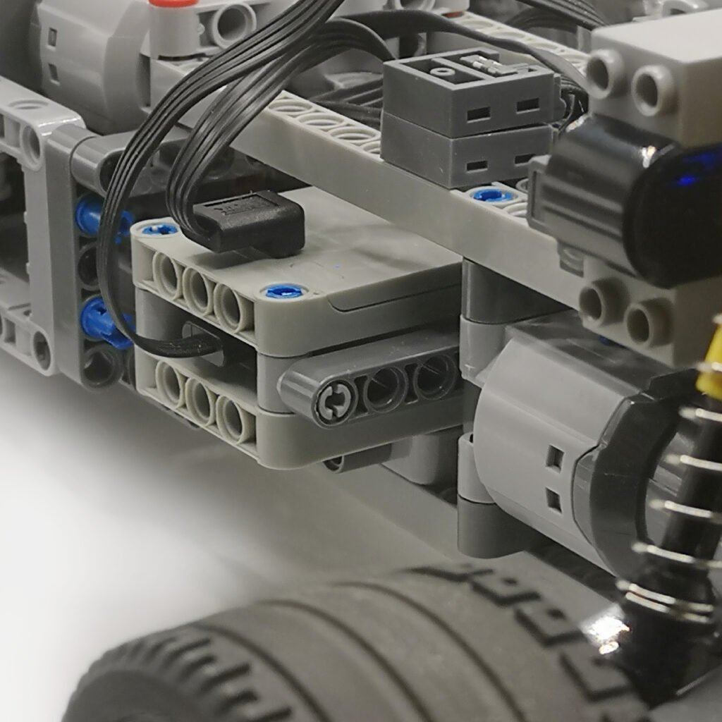
Do not pull, twist or sharply bend the FynoriX PF Output Cable near either connector.
Confirm that all PF connectors are correctly aligned and fully seated before switching on the system.
The compact structure of FynoriX1511 allows it to be positioned in different areas of the model. Select the installation location according to the model’s internal space, weight distribution and service requirements.
The battery should adapt to the model—not the model to the battery.
4.3 Power Button and Low-Voltage Output
The FynoriX1511 power button enables or disables the regulated 9 V output circuit.
When FynoriX1511 is switched on, the regulated circuit provides 9 V through the dedicated output port and connected FynoriX PF Output Cable.
When FynoriX1511 is switched off, the regulated 9 V circuit is disabled, but the output is not completely isolated electrically. Because of the customised internal cell and circuit architecture, a low-voltage output may remain at the connected PF output.
A motor connected directly to the FynoriX PF Output Cable may therefore continue turning slowly after the power button is switched off. This is a normal operating characteristic rather than a product fault.
For predictable control, connect FynoriX1511 to a compatible PF switch, receiver or controller first, then connect the motor or electrical load after that controlled component.
The power button should not be treated as a complete electrical-isolation switch. Disconnect the electrical load or output cable before storage, transport or work on the model.
4.4 Mechanical Operating Recommendations
The electrical and mechanical systems should be evaluated together.
For efficient operation:
- ensure gears are correctly aligned;
- allow axles to rotate freely;
- reduce unnecessary drivetrain resistance;
- select a gear ratio appropriate for the load;
- prevent wheels, tracks and moving mechanisms from binding;
- avoid holding motors against mechanical endpoints;
- avoid prolonged or repeated stall operation.
A motor approaching stall can draw substantially more current than during normal rotation.
This is particularly relevant during startup, when a heavy or resistant mechanism may briefly place the motor close to its stall condition.
Where high startup demand is a normal characteristic of the application, use the appropriate configuration described in Chapter 3.4.5 Continuous External Power Applications
For fixed applications that do not require battery operation, a USB-C to PF Adapter may be used as an alternative external power source.
Typical applications include:
- exhibitions;
- display models;
- train layouts;
- continuous lighting;
- GBC systems;
- workbench motor testing;
- long-duration demonstrations.
Use the adapter only with a compatible USB-C PD power source capable of providing regulated 9 V output.
The USB-C to PF Adapter is an independent power source. It is not part of a FynoriX1511 capacity-expansion or Stacked PF Output configuration.
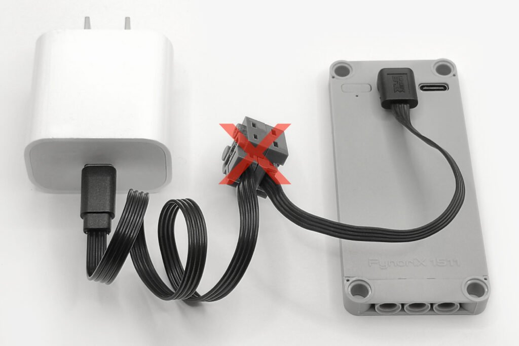
Never connect the adapter to a PF circuit that is already powered by:
a FynoriX1511;
a traditional Power Functions battery box;
another USB-C to PF Adapter;
another battery or external power supply.
Different powered sources must not be electrically combined in the same PF circuit.
4.6 Understanding Normal Protection Behaviour
FynoriX1511 includes an internal protection system designed to help protect the energy module and connected equipment when the operating demand exceeds an applicable limit.
Protection may activate when a motor briefly approaches stall because of:
- unusually high startup resistance;
- a blocked mechanism;
- several motors starting simultaneously;
- excessive mechanical load;
- repeated rapid direction changes.
High startup demand may also occur in a correctly designed model when substantial vehicle mass, tyre grip, gearing or mechanical inertia temporarily prevents the motor from accelerating.
As shown in Chapter 2, motor current can increase significantly near stall and may be several times higher than normal running current.
If this demand exceeds the short-term operating range of the selected configuration, FynoriX1511 may interrupt its output as intended.
This is a normal protective response to the motor and mechanical operating condition. It does not by itself indicate that the energy module is defective.
If protection activates:
connect FynoriX1511 to a charging source using the recommended USB-A-to-USB-C connection for approximately one second to reset the protection circuit;
- fully charge the module before further high-load testing;
- review the configuration guidance in Chapter 3.
Do not repeatedly restart a motor that is blocked or held near stall.
4.7 General Safety Notes
Use FynoriX1511 only with compatible Power Functions-style devices and intended connection methods.
Do not electrically combine FynoriX1511 with:
- traditional Power Functions battery boxes;
- USB-C to PF Adapters;
- different-voltage power supplies;
- incompatible battery systems;
- other powered PF devices.
When using InfiLinX Capacity Expansion with FynoriX1511:
- InfiLinX is not hot-pluggable;
- fully charge each module separately before connection;
- make sure all modules have a similar state of charge;
- switch OFF all connected modules before connecting, disconnecting, or reconfiguring InfiLinX;
- build the complete InfiLinX chain first and confirm that all connectors are fully inserted;
- only then power on the modules;
- never connect or disconnect InfiLinX while any connected module is powered on;
- disconnect the complete InfiLinX chain before charging;
- charge each module separately through its own USB-C charging port;
- do not use InfiLinX as a charging interface.
When using Multi-Battery Stacked PF Output:
- use only FynoriX1511 modules in the same stacked output configuration;
- fully charge each module separately before connection;
- make sure all modules have a similar state of charge;
- use one FynoriX PF Output Cable for each module;
- inspect all cables and connectors;
- disconnect the system before changing the configuration.
Stop using the affected component if any of the following is observed:
- damaged insulation;
- exposed conductors;
- connector deformation;
- physical swelling;
- liquid exposure;
- unusual odour;
- abnormal heating during light-load operation.
Do not open, modify or attempt to repair the FynoriX1511 enclosure.
4.8 Best Practices
For the best overall system performance:
- begin with the simplest configuration suitable for the application;
- fully charge the energy module before demanding operation;
- use InfiLinX Capacity Expansion with FynoriX1511 when greater capacity and longer runtime are required;
- use Multi-Battery Stacked PF Output when greater available power is required during short-duration startup demand;
- use the USB-C to PF Adapter when continuous external power is preferred;
- optimise the mechanical system before increasing the power configuration;
- test the completed model under realistic operating conditions;
- use only one supported power configuration on the same PF circuit.
Different applications require different power methods.
Selecting the appropriate method is part of the normal model-design process.
4.9 Final Summary
FynoriX1511 was designed as a compact modular energy unit rather than a traditional integrated battery box.
Its modular architecture allows builders to select the power method that best matches the application:
- a single FynoriX1511 for standard and compact models;
- InfiLinX Capacity Expansion with FynoriX1511 for greater capacity and longer operating time;
- Multi-Battery Stacked PF Output for greater available power during short-duration startup demand;
- a USB-C to PF Adapter for continuous external power applications.
Protection behaviour should be understood within the complete system.
When a motor approaches stall because of high startup resistance or mechanical load, its current demand may exceed normal operating levels. The protection system responds by interrupting the output within the defined operating limits of the energy module.
By combining the appropriate power configuration with efficient mechanical design, FynoriX1511 can support a wide range of model types and operating requirements.
There is no universal power solution—only the solution that best matches the application.
Related Products & Resources
FynoriX1511 Power Brick
Product specifications, package options and purchasing information.
https://conceptbrick.com/product/fynorix1511-power-brick/
FynoriX PF Output Cable
Dedicated PF output connection and Multi-Battery Stacked PF Output information.
https://conceptbrick.com/product/fynorix-pf-output-cable/
InfiLinX Modular Connection Cable
Capacity-expansion connection for compatible FynoriX1511 modules.
https://conceptbrick.com/product/infilinx/
USB-C to PF Adapter
External 9V power solution for compatible fixed displays, GBC modules and testing applications.
https://conceptbrick.com/product/typec-to-pf-adapter/