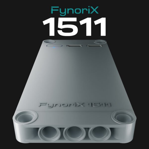
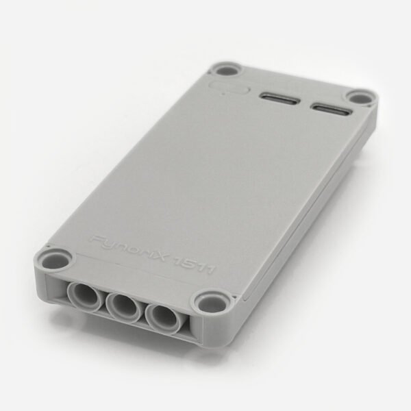
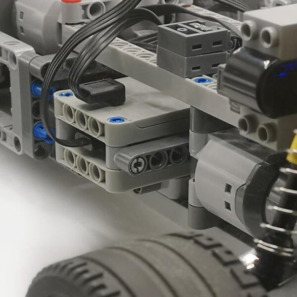
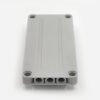
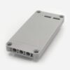
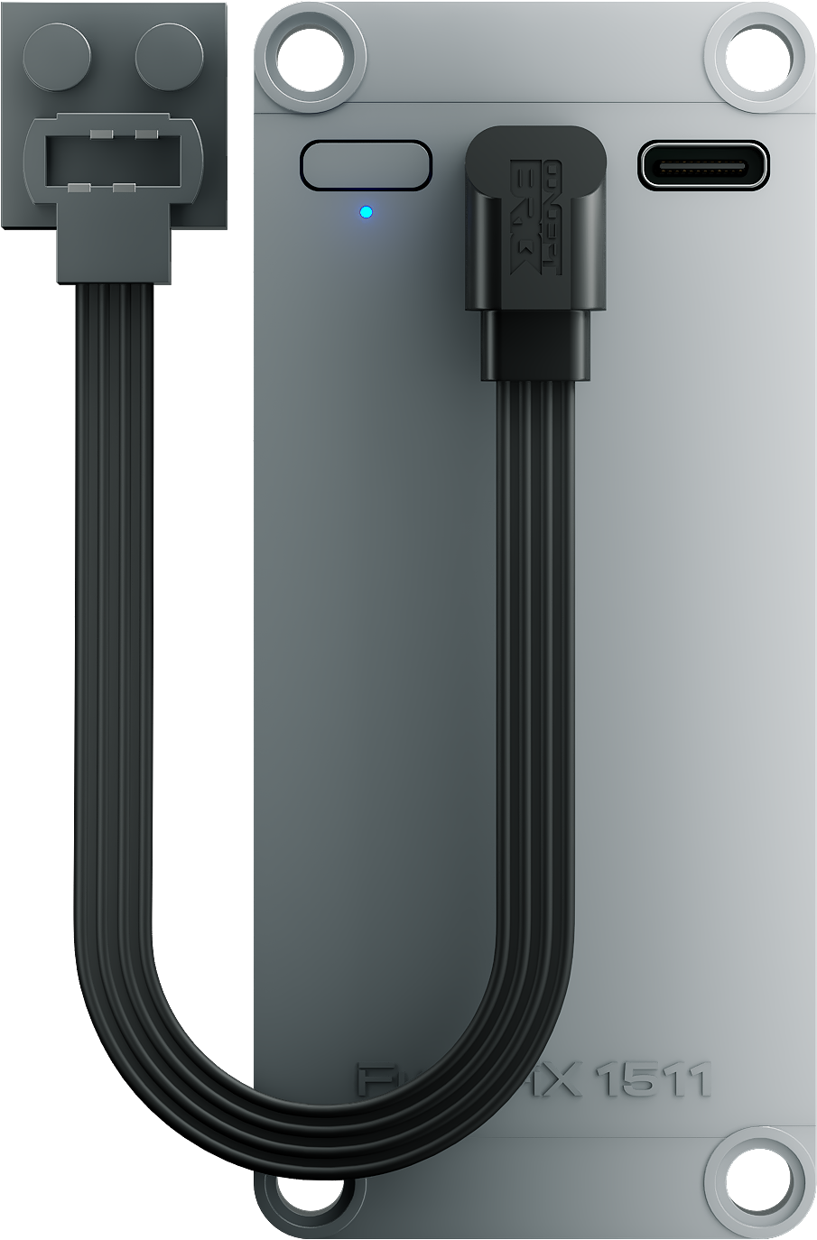
FynoriX1511 is a compact, rechargeable 9V modular energy module designed for PF-compatible motors, receivers, switches and lights. Its 7.8 mm profile, 35 g weight and 5 × 11 panel-compatible format allow it to fit into compact chassis, bodywork and other space-constrained structures.
• Regulated 9V output
• 4800mWh capacity
• Up to 1.7A short-term peak current
• 5 × 11 panel-compatible footprint
Choose 1PC, 2PCs or 4PCs above. Not compatible with Powered Up or Control+.
⚠ Important — InfiLinX is not hot-pluggable.
Always switch OFF all FynoriX1511 modules before connecting or disconnecting an InfiLinX cable. Fully connect the InfiLinX cable first, then power on the modules. Connecting or disconnecting InfiLinX while a module is powered on may damage the charging/input circuitry.
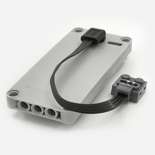
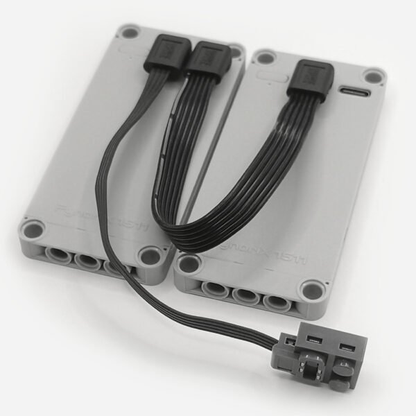
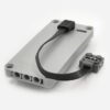
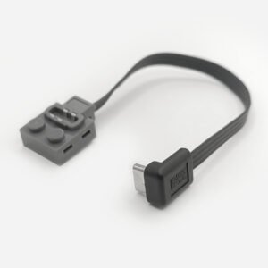
1 × FynoriX1511 energy module and 1 × FynoriX PF Output Cable
2PCs
1 × Dual Battery Set
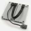
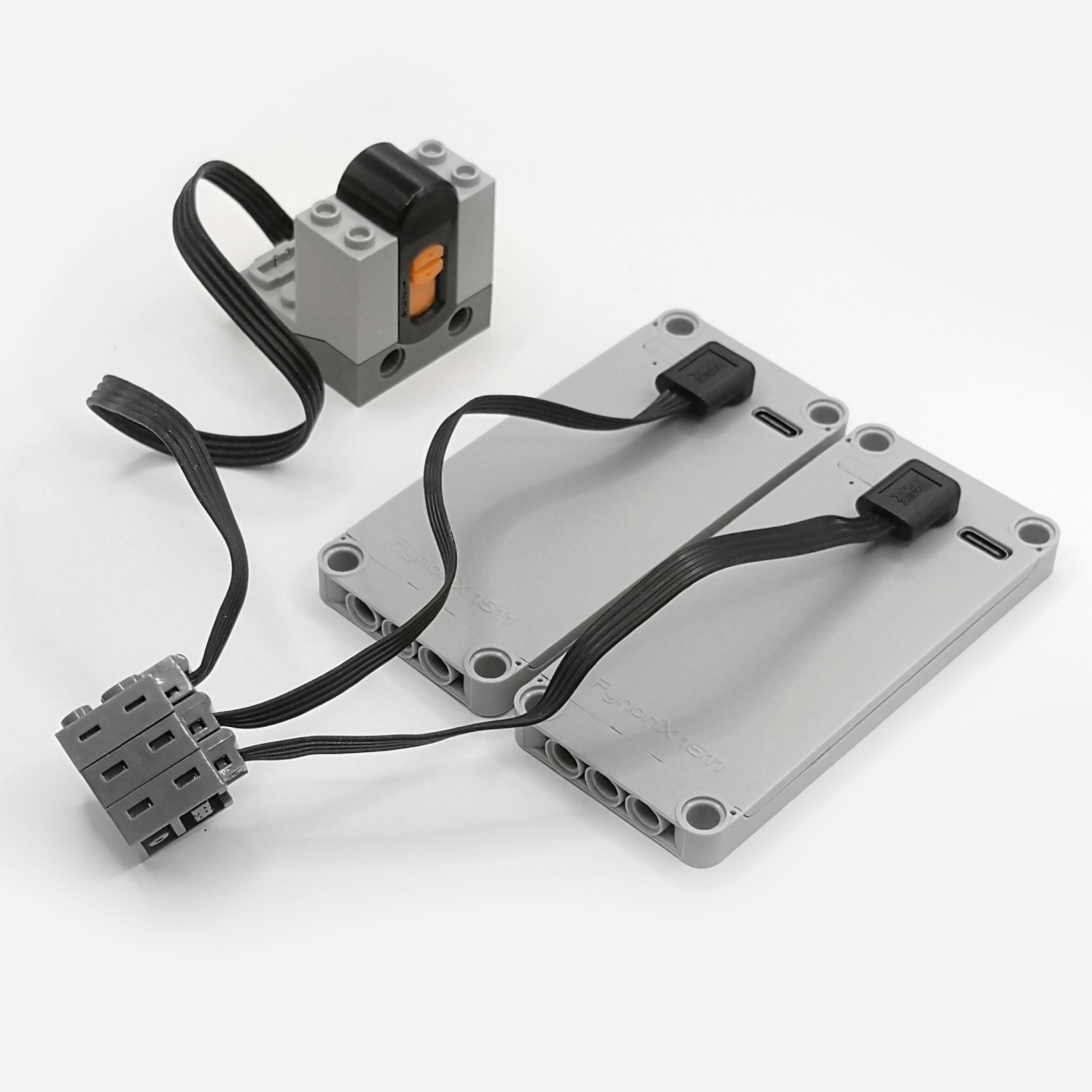
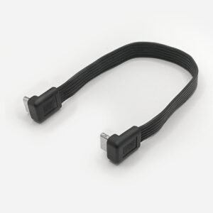
2 × FynoriX1511 energy modules, 2 × FynoriX PF Output Cables and 1 × InfiLinX cable
4PCs
2 × Dual Battery Sets
4 × FynoriX1511 energy modules, 4 × FynoriX PF Output Cables and 2 × InfiLinX cables
Important: The 4PCs option consists of two complete Dual Battery Sets. It is not packaged as one four-battery set and therefore includes two InfiLinX cables. A USB-A-to-USB-C charging cable, USB charger, power bank, PF receiver, switch, controller and motor are not included.
Charging Requirements
Charge FynoriX1511 through its USB-C charging port using a standard USB-A-to-USB-C charging cable connected to a USB-A charger or a power bank with a USB-A output.
Ultra-Slim
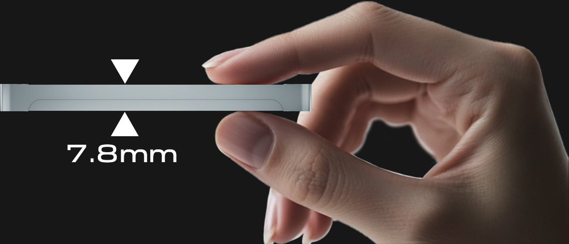
At only 7.8 mm—approximately one stud thick—it fits easily into compact and space-constrained builds.
Ultra-Light
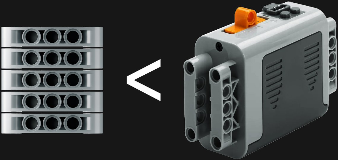
At only 35 g, it keeps your models light and agile.
Panel Compatible
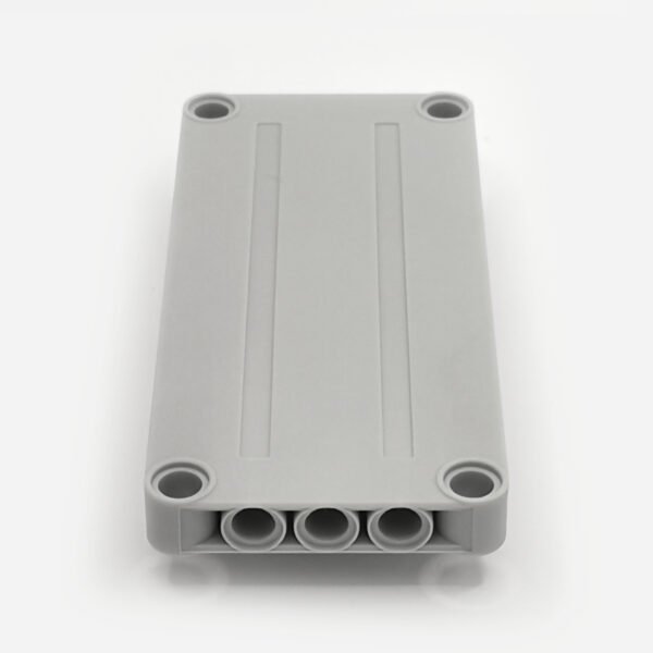
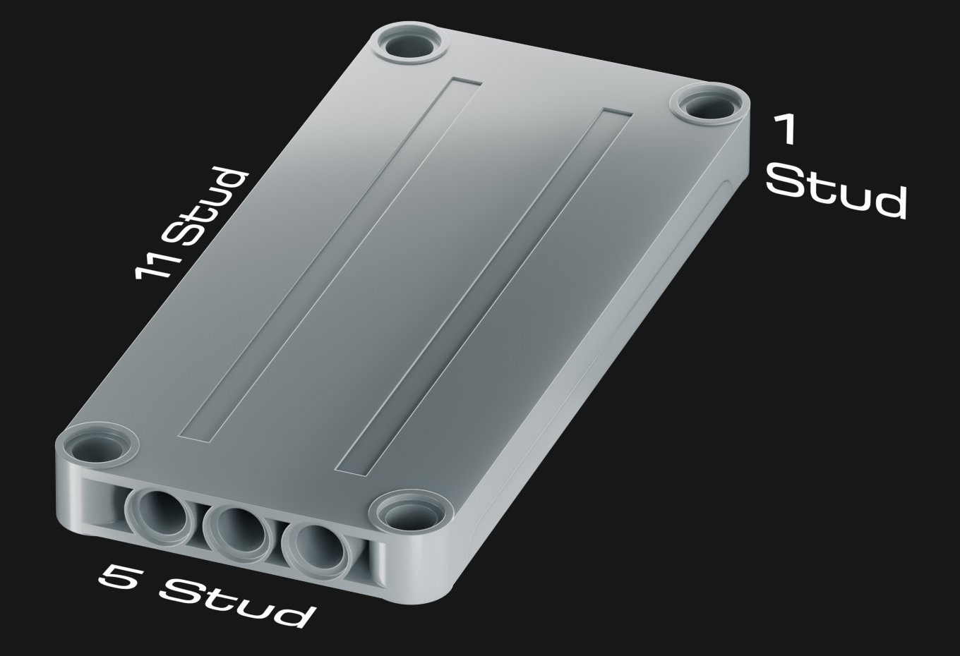
Designed around a 5 × 11 Technic-style panel footprint, FynoriX1511 includes ten mounting holes for flexible positioning and secure installation within a model. It is intended to be supported by the surrounding structure rather than used as a replacement for a structural panel or as a primary load-bearing component.
Please click the link below to download the data file for this product. This will allow you to integrate the product into your building designs in Studio 2.0.
Regulated 9V Power
Provides regulated 9 V DC output with up to 15.3 W short-term peak power for compatible motorized building block devices.
For detailed motor-current references, configuration selection and high-load guidance, see the FynoriX1511 Engineering Guide.
High Energy for Its Size
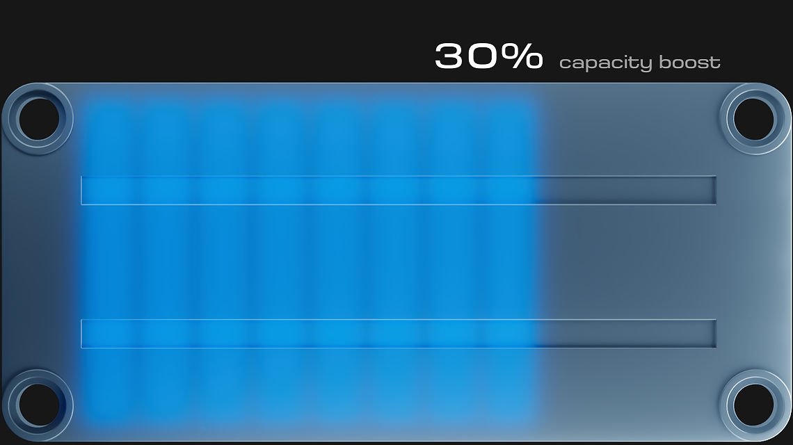
4800 mWh high capacity, delivering up to 30% more energy than same-size cells for longer-lasting power.
InfiLinX Capacity Expansion
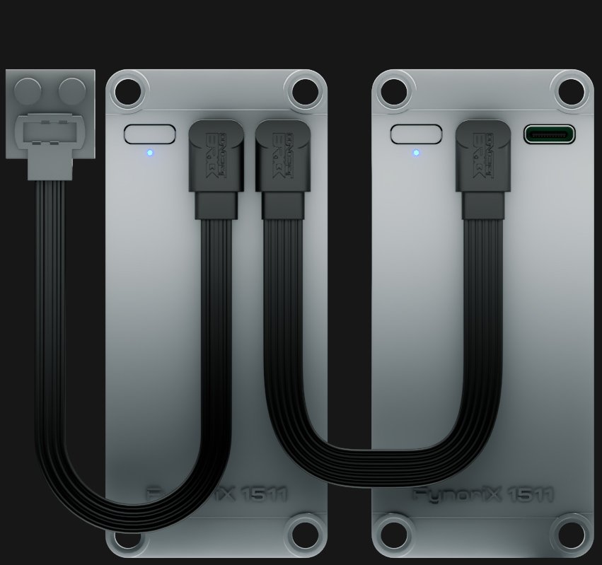
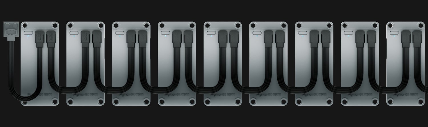
In the current FynoriX1511 configuration, connect two or more energy modules through InfiLinX to increase total stored energy and extend operating time. InfiLinX is part of a broader modular connection system and does not increase the peak current available from a single PF output.
FynoriX1511 Quick Engineering Guide
Important Safety Notice: InfiLinX is not hot-pluggable. Always switch OFF all FynoriX1511 modules before connecting or disconnecting InfiLinX.
1. An Independent Energy Module
FynoriX1511 was designed as the smallest independent energy unit in the system. It provides regulated 9 V power but does not control motor direction or speed.
Use the following system structure:
FynoriX1511 → Switch / Receiver / Controller → Motor or Electrical Load
The battery provides power, the controller controls, and the motor creates movement. Separating these functions allows the thin energy module to be positioned wherever suitable space is available.
The battery should adapt to the model—not the model to the battery.
Power Functions compatibility is only the starting point. FynoriX1511 is intended to become the energy foundation of a future modular electrical ecosystem.
2. Important Power-Off Behaviour
When FynoriX1511 is switched off, its regulated 9 V circuit is disabled, but the output is not completely electrically isolated. A low voltage may remain at the PF output.
A motor connected directly to the energy module may therefore continue turning slowly after it is switched off. This is a normal product characteristic.
For predictable start and stop control, always connect a compatible PF switch, receiver or controller between FynoriX1511 and the motor.
Disconnect the electrical load before storage, transport, charging or work on the model.
3. Choose the Right Configuration
Application requirement
Recommended configuration
Purpose
Compact or standard model
Single FynoriX1511
Recommended starting point for most light- and medium-load applications
Longer operating time
InfiLinX Capacity Expansion
Increases total stored energy and extends runtime. Connect only while all modules are powered OFF
Heavy startup or several motors starting together
Multi-Battery Stacked PF Output
Provides greater available power for short-duration startup demand
InfiLinX Capacity Expansion
Use InfiLinX when one module provides sufficient performance but longer runtime is required.
Important — InfiLinX is not hot-pluggable.
Always switch OFF all FynoriX1511 modules before connecting, disconnecting, or reconfiguring an InfiLinX connection.
Connect the complete InfiLinX chain first, make sure all connectors are fully inserted, and only then power on the modules.
Never connect an InfiLinX cable to a module while another connected module is already powered on. Hot-plugging may damage the charging/input circuitry.
Example with three modules:
P3 OUT → P2 IN P2 OUT → P1 IN P1 PF Output → Switch / Receiver / Controller → Motor or Electrical Load
Power OFF → Connect the complete InfiLinX chain → Power ON
For additional modules, continue the chain toward P1.
InfiLinX increases total stored energy and runtime. The main PF output remains regulated at 9 V, and the peak current available from a single PF output does not increase.
Multi-Battery Stacked PF Output
For models with greater startup demand, connect each FynoriX1511 using its own PF Output Cable and stack the PF connectors directly together. Connect the compatible switch, receiver or controller after the stacked connection.
The output remains regulated at 9 V. Available current or power should not be assumed to increase linearly with the number of connected modules.
These configurations serve different purposes:
Use InfiLinX for more capacity and longer runtime.
Use Stacked PF Output for greater short-duration startup support.
4. Motor Compatibility at a Glance
Motor
Observed Free-Running Current
Observed Peak Current*
General guidance
PF Micro Motor
0.1 A
0.6 A
✅ Recommended for normal light-duty applications
PF M Motor
0.13 A
1.5 A
✅ Recommended for most applications with an efficient mechanism
PF L Motor
0.17 A
2.7 A
⚠ Application dependent on gearing, model weight and motor quantity
PF XL Motor
0.14 A
2.5 A
⚠ Application dependent, particularly in heavy or tracked models
PF Buggy Motor
0.14 A
2.8 A
🔧 Requires model-specific evaluation
Motor type alone does not determine the required configuration. Vehicle weight, gearing, friction, drivetrain efficiency and simultaneous motor startup can substantially change electrical demand.
Begin with one fully charged FynoriX1511 and test the completed model under realistic operating conditions. Correct unnecessary drivetrain resistance before adding more energy modules.
5. Charging, Protection and Safety
Important — InfiLinX is not hot-pluggable.
Always switch OFF all connected FynoriX1511 modules before connecting, disconnecting, or reconfiguring an InfiLinX connection.
Connect the complete InfiLinX chain first, make sure all connectors are fully inserted, and only then power on the modules.
Never connect or disconnect InfiLinX while any connected module is powered on. Hot-plugging InfiLinX may permanently damage the charging/input circuitry of a connected FynoriX1511 module.
Before charging, connecting, disconnecting, or reconfiguring multiple modules:
switch off all connected modules;
never connect or disconnect InfiLinX while any connected module is powered on;
connect the complete InfiLinX chain before powering on;
charge each module separately;
use modules with a similar state of charge;
inspect all cables and connectors;
disconnect the complete InfiLinX chain before charging.
If protection interrupts the output:
Connect FynoriX1511 to a charger for approximately one second to reset the protection circuit.
Fully charge the module.
Check the drivetrain for binding, excessive resistance or an unsuitable gear ratio.
Do not repeatedly restart a blocked or stalled motor.
Never combine FynoriX1511 with a traditional PF battery box, USB-C to PF Adapter, external power supply or another powered device on the same PF circuit.
Do not open, modify or use a damaged FynoriX1511 module or cable.
Need More Technical Detail?
For motor-current references, detailed configuration diagrams, mechanical optimisation and operating guidance, read the:
Q: What is FynoriX1511?
A: FynoriX1511 is a compact rechargeable 9 V modular energy module designed for PF-compatible Technic and MOC systems. Its slim 5 × 11 panel-compatible footprint allows it to be positioned in space-constrained models.
Q: What output voltage does FynoriX1511 provide?
A: It provides regulated 9V DC output.
Q: Why can a motor continue turning slowly after FynoriX1511 is switched off?
A: The power button disables the regulated 9V circuit, but it does not completely electrically isolate the internal cell from the PF output. Because of the customised cell and circuit architecture, a low-voltage output remains at the connector. A motor connected directly to FynoriX1511 may therefore continue turning slowly. This is a normal product characteristic rather than a fault. For normal operation, connect FynoriX1511 to a compatible PF switch, receiver or controller first, and connect the motor after that controlled component.
Q: What is the battery capacity?
A: FynoriX1511 has a 4800mWh internal rechargeable battery.
Q: Why does the indicator remain red after I connect the charger?
A: If FynoriX1511 is switched on while the battery level is low, the red low-battery indication takes priority over the blue charging indication. The module may still be charging, and the indicator will turn green when fully charged. Switch off FynoriX1511 and disconnect the load before charging to obtain the normal blue charging indication.
Q: What is the maximum output current?
A: The maximum output current is up to 1.7A short-term peak. Avoid stalled motors, overloaded drivetrains, or continuous operation near the peak current limit.
Q: Why are some measured motor-current peaks higher than the 1.7 A output rating of FynoriX1511?
A: The test values represent the current demanded by specific motors during a simulated high-resistance startup condition. They do not represent current continuously supplied by one FynoriX1511. If the demand exceeds the short-term operating range of the selected configuration, the protection system may interrupt the output. Actual demand depends on the complete mechanical system.
Q: Why may protection activate during motor startup?
A: In some applications, high startup resistance may briefly place a motor close to stall. Its instantaneous current can then rise substantially above the normal running level. If the demand exceeds the short-term operating range of the selected configuration, the internal protection system may interrupt the output as intended.
Q: Why does the red indicator appear during operation, or why does protection interrupt the output shortly after startup?
A: First, make sure FynoriX1511 is fully charged and that the drivetrain or connected mechanism can move freely. A red indication or protective shutdown during operation may be caused by excessive mechanical resistance, an overloaded drivetrain or a motor or other electrical load drawing abnormally high current. Switch off FynoriX1511, disconnect the load and do not repeatedly restart the system. After checking the mechanism and connections, test the same setup with another known-good compatible motor or electrical load. If the problem no longer occurs, the original component may be damaged even if it can still operate.
Q: How much does FynoriX1511 weigh?
A: It weighs approximately 35g, making it suitable for lightweight Technic and MOC builds.
Q: How thick is FynoriX1511?
A: It is approximately 7.8mm thick, which is about 1 stud thick.
Q: Can multiple FynoriX1511 units be used together?
A: Yes. FynoriX1511 supports two different multi-module power configurations. When used with FynoriX1511, InfiLinX Capacity Expansion increases total stored energy and operating time. Multi-Battery Stacked PF Output allows multiple FynoriX1511 modules to contribute to the same PF circuit when greater short-duration startup power is required. These configurations serve different purposes.
Q: Is InfiLinX only a battery-capacity expansion connection?
A: No. InfiLinX is a modular interconnection interface for compatible components within the expanding CONCEPTBRICK electrical ecosystem. Depending on the connected modules and configuration, it may carry power or control signals, while future compatible applications may also support data transmission. When used with FynoriX1511, its current function is to increase total battery capacity and extend runtime. InfiLinX is not a charging interface.
Q: Does FynoriX1511 control motor direction?
A: No. The power button enables or disables the regulated 9V output circuit, but it does not control motor direction or speed and does not provide complete electrical isolation at the PF output. Normal start, stop, direction and speed control should be managed by a compatible external switch, receiver or controller.
Q: What is the difference between FynoriX1511 and the USB-C to PF Adapter?
A: FynoriX1511 is an onboard rechargeable 9 V modular energy module designed to be built into a model. The USB-C to PF Adapter is an external power adapter used with a compatible USB-C PD power source.
Q: What models is FynoriX1511 best for?
A: It is best for compact Technic MOCs, RC-style vehicles, crawlers, robots, motorized display models, and builds where a traditional battery box is too large or difficult to access.
Q: Can FynoriX1511 power an SBrick?
A: Yes. FynoriX1511 provides regulated 9V power through its Power Functions-compatible output, making it suitable as an independent energy module for existing SBrick systems. Connect the system as follows:
FynoriX1511 → SBrick → Motor or Electrical Load
Available system current remains limited by the output capability of the connected FynoriX1511 configuration and the electrical demand of the complete model.
Some product images are renderings for reference only. The actual product may vary slightly in appearance; please refer to the physical product received.
Learn more about USB-C and Power Delivery standards from the USB Implementers Forum (USB-IF).
Reviews
There are no reviews yet.
Reviews can only be submitted by verified customers who have purchased this product.




Reviews
There are no reviews yet.